【Juniper(JUNOS)】EXシリーズ 特定通信のAnalyzer
JuniperのEX4200で特定の通信のみミラーしパケットキャプチャする設定を記載します。
※検証で使用した機器はEX4200(JUNOS:9.5R3.7)です。
構成は下図の通り。
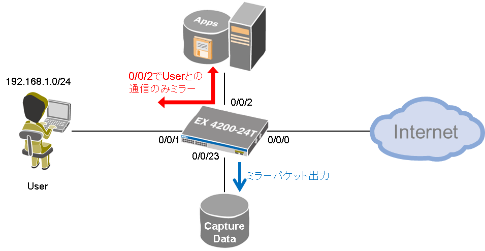
上図のInterface 0/0/2でUserのトラフィックのみをミラーしたい場合の設定です。
※通常の通信は既に可能である前提です。
set interfaces ge-0/0/1 unit 0 family inet filter input USER-Src-Traffic
set interfaces ge-0/0/2 unit 0 family inet filter input USER-Dst-Traffic

set firewall family inet filter USER-Src-Traffic term 1 from source-address 192.168.1.0/24
set firewall family inet filter USER-Src-Traffic term 1 then analyzer TEST
set firewall family inet filter USER-Src-Traffic term 1 then accept
set firewall family inet filter USER-Src-Traffic term 2 then accept

set firewall family inet filter USER-Dst-Traffic term 1 from destination-address 192.168.1.0/24
set firewall family inet filter USER-Dst-Traffic term 1 then analyzer TEST
set firewall family inet filter USER-Dst-Traffic term 1 then accept
set firewall family inet filter USER-Dst-Traffic term 2 then accept

set ethernet-switching-options analyzer TEST output interface ge-0/0/23.0
注)必要のないトラフィックをミラーさせない設定はできません。
InterfaceにoutputのAnalyzerが関わるFilterを設定することはできません。
【FortiGate】IPSec-VPN設定(with NAT)~Site-to-Site編~
FortiGateでIPSec-VPNの設定をして且つローカルアドレスのSorce IPをNAT変換してみたので設定方法を記載します。
※検証で使用した機器はFortiWiFi90D(Ver:5.2.3)です。
構成は下図の通り。

※各InterfaceのIPアドレス等は設定済みという前提
①VPN設定(Center側)
VPN>IPSec>ウィザード
任意の名前を記入し「Site-to-Site」を選択して「次へ」
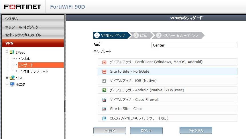
下図4項目を記入し「次へ」
リモートゲートウェイ:トンネルの対向のIPアドレス
出力インターフェース:トンネルを張る自Interface

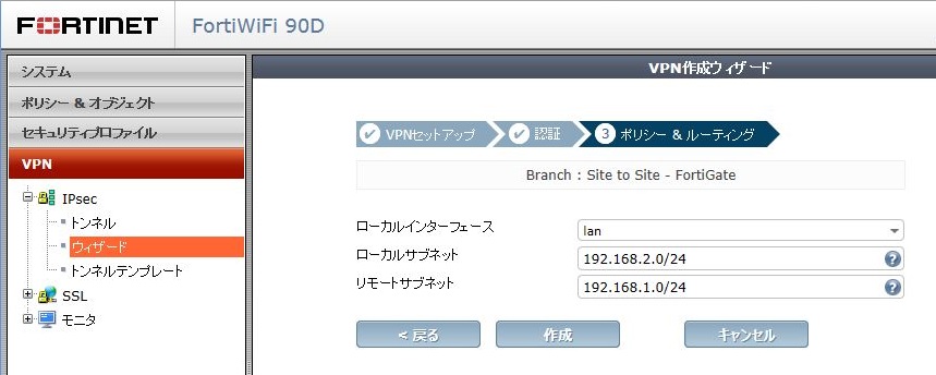
下図3項目を記入し「次へ」
ローカルインターフェース:自LAN側Interface
ローカルサブネット:自LAN側NW
リモートサブネット:対向の宛先NW

②VPN設定(Branch側)
VPN>IPSec>ウィザード
任意の名前を記入し「Site-to-Site」を選択して「次へ」

下図4項目を記入し「次へ」
リモートゲートウェイ:トンネルの対向のIPアドレス
出力インターフェース:トンネルを張る自Interface
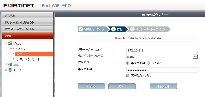
下図3項目を記入し「次へ」
ローカルインターフェース:自LAN側Interface
ローカルサブネット:自LAN側NW
リモートサブネット:対向の宛先NW
③疎通確認
LAN-to-LANでPINGを実施することでInterest Packetが送出されIPSecのステータスがアップします。
VPN>モニタ>IPSecモニタ

④ローカルアドレスのSorce IPをNAT変換
ポリシー&オブジェクト>ポリシー>IPv4
構成図のようにNAT変換させる場合、Center側のFortiGateでトンネルInterfaceからLANへ通過するポリシーに対してNAT設定する

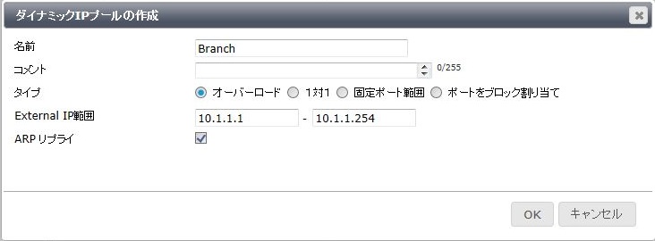
この構成であればBranchからCenterへアクセスする通信はIPSecトンネルを通り、且つSorceIPがNAT変換される。
NAT変換されたことを確認するには方法がいくつかありますが代表的な2つを紹介します。
■セッションテーブルの確認
FortiGate # diagnose sys session filter src 192.168.2.1

FortiGate # diagnose sys session list

session info: proto=1 proto_state=00 duration=2 expire=57 timeout=0 flags=00000000 sockflag=00000000 sockport=0 av_idx=0 use=3
origin-shaper=
reply-shaper=
per_ip_shaper=
ha_id=0 policy_dir=0 tunnel=/Center
state=may_dirty npu
statistic(bytes/packets/allow_err): org=500/5/1 reply=500/5/1 tuples=2
orgin->sink: org pre->post, reply pre->post dev=69->63/63->69 gwy=192.168.1.1/192.168.2.1
hook=post dir=org act=snat 192.168.2.1:15->192.168.1.1:8(10.1.1.1:62464)
hook=pre dir=reply act=dnat 192.168.1.1:62464->10.1.1.1:0(192.168.2.1:15)
misc=0 policy_id=3 auth_info=0 chk_client_info=0 vd=0
serial=0000036e tos=ff/ff ips_view=0 app_list=0 app=0
dd_type=0 dd_mode=0
npu_state=00000000
npu info: flag=0x00/0x82, offload=0/0, ips_offload=0/0, epid=0/0, ipid=0/0, vlan=0/0
total session 1

FortiGate # diagnose sys session filter clear
■パケット処理フローの確認
FortiGate # diagnose debug flow show console enable
show trace messages on console

FortiGate # diagnose debug flow filter proto 1  ←ICMPの場合、プロトコル番号は「1」

FortiGate # diagnose debug flow trace start 2  ←出力させる項目数(指定なしの場合は1項目表示)

id=20085 trace_id=1 func=print_pkt_detail line=4378 msg="vd-root received a packet(proto=1, 192.168.2.1:18->192.1"
id=20085 trace_id=1 func=init_ip_session_common line=4527 msg="allocate a new session-000003e7"
id=20085 trace_id=1 func=vf_ip4_route_input line=1596 msg="find a route: flags=00000000 gw-192.168.1.1 via lan"
id=20085 trace_id=1 func=fw_forward_handler line=670 msg="Allowed by Policy-3: SNAT"
id=20085 trace_id=1 func=__ip_session_run_tuple line=2523 msg="SNAT 192.168.2.1->10.1.1.1:60418"
id=20085 trace_id=1 func=__if_queue_push_xmit line=366 msg="send out via dev-internal, dst-mac-00:1b:d3:8a:7e:e2"
id=20085 trace_id=2 func=print_pkt_detail line=4378 msg="vd-root received a packet(proto=1, 192.168.1.1:60418->10.1.1.1:0) from la"
id=20085 trace_id=2 func=resolve_ip_tuple_fast line=4437 msg="Find an existing session, id-000003e7, reply direction"
id=20085 trace_id=2 func=__ip_session_run_tuple line=2537 msg="DNAT 10.1.1.1:0->192.168.2.1:18"
id=20085 trace_id=2 func=vf_ip4_route_input line=1596 msg="find a route: flags=00000000 gw-192.168.2.1 via Center"
id=20085 trace_id=2 func=ipsecdev_hard_start_xmit line=121 msg="enter IPsec interface-Center"
id=20085 trace_id=2 func=ipsec_output_finish line=232 msg="send to 172.16.1.2 via intf-wan1"
id=20085 trace_id=2 func=esp_output4 line=889 msg="encrypting, and send to 172.16.1.2 with source 172.16.1.1"
~[省略]~

FortiGate # diagnose debug flow filter clear
【FortiGate】マルチホーム設定(WAN冗長化)
FortiGateでマルチホーム構成にしてみたので設定方法を記載します。
※検証で使用した機器はFortiWiFi90D(Ver:5.2.3)です。
構成は下図の通り。

①各Interfaceの設定
②WANリンクロードバランスの設定
※ポリシー等にWANリンクが設定されていると設定ができないので事前に削除する必要がある
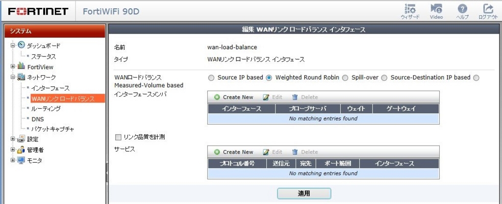
・WANロードバランス方法を選択
(今回はActive/Standbyとして設定したいので「Weighted Round Robin」を選択)
・インターフェースメンバの登録(「Creat New」をクリックして新規登録)
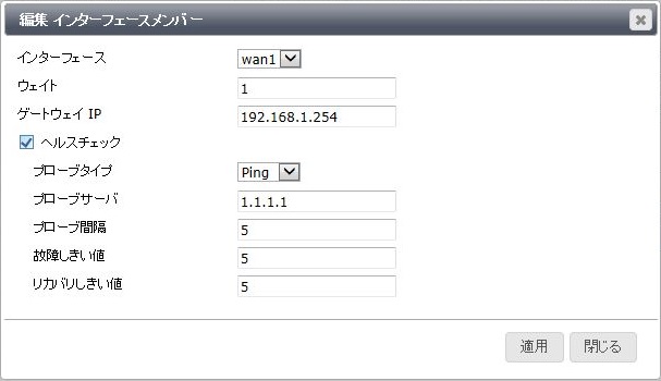
・各値を入力
ウェイト:バランシングの比率
ゲートウェイIP:ルーティング上のネクストホップの値
プローブサーバ:死活監視対象のIPアドレス
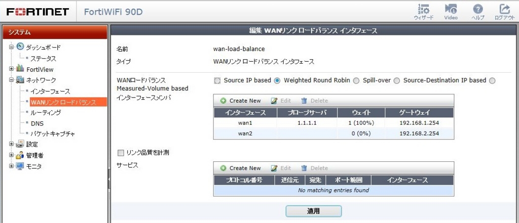
※今回はActive/Standbyとする為、比率は1:0としStandby側のヘルスチェックは必要ない。
③ルーティング設定
※デバイスは「wan-load-balance」を選択するとゲートウェイはWANリンクロードバランスで設定した値になるのでここでは設定できない
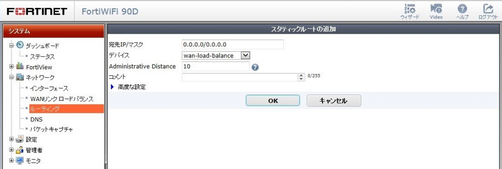
④ポリシー設定
※インターフェースは「wan-load-balance」とする
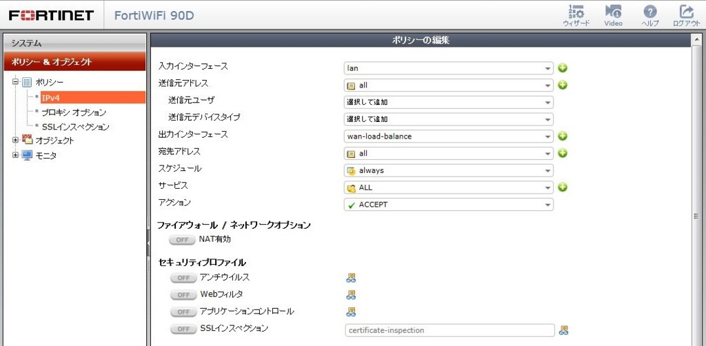
通信はウェイト値(バランシングの比率)で振り分けらる。
今回はActive/Standbyとした為、比率は1:0としActive側のヘルスチェックがNGにならない限りStandby側には通信は転送されない。
Active/Activeとしたい場合は比率を1:1とすれば同量の通信を振り分けることとなる。
【FortiGate】NATを有効化した場合のFTP通信(パッシブモード)
NATを有効化した場合のFTP通信(パッシブモード)において不具合があり調査した結果FortiGateの仕様で判明したことがあるので記載します。
簡単な構成例は下図の通りです。

FTPサーバは公開サーバとしてFortiGateにVirtual IPを設定して宛先をNATする設定にしています。
FTP通信(パッシブモード)は簡単に説明すると下図のようにサーバからデータをやりとりするためのport番号を通知してもらいクライアントはそのport番号でサーバへアクセスします。
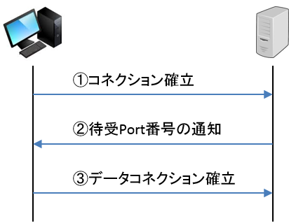
ここでFortiGateの仕様によりNAT有効またはVirtual IPを使用している場合はこのport番号もランダムに変換されてしまいます。
もしクライアントとサーバ間でRouterやファイアウォール製品が存在してポート番号で制限している場合は注意が必要です。
ランダムでポート番号を変換されるためTCP1024~65535等のHigtポートを許可する必要があります。
NATの送信元ポート番号の範囲はメーカーのナレッジに公開されています。
【FortiGate】Firmware(OS Version)のダウングレード方法
FortiGateでFirmware(OS)のダウングレードを実施しました。
各機種で方法が若干異なるのでそれぞれ記載します。
今回はFortiWiFi60D、FortiWiFi90D、FortiGate240Dで下記Versionにダウングレードを実施しました。
FortiWiFi60D:ver5.2.4→ver5.0.11
FortiWiFi90D:ver5.2.4→ver5.0.9
FortiGate240D:ver5.2.4→ver5.0.11
※このダウングレード方法はConfigが工場出荷時に初期化されてしまうので事前にバックアップを取得することをお奨めします。
■準備物
・ダウングレードするFortiOS
・TFTPサーバ(PCに「3CDaemon」をインストールして実施しました。)
・コンソールケーブル
■FortiOSダウングレード手順
[FortiWiFi60D、FortiWiFi90D]
①、PCとデバイスをコンソール接続してターミナルソフトを起動
②、TFTPサーバを起動させ、アップロードフォルダへ該当のOSファイルを保存する
(注1)OSファイル名は"image.out"に変更しておく。
(注2)PCのIPアドレスは192.168.1.100/24に設定しておく。
③、機器を再起動 ※下記実例参照
④、起動中の下記メッセージ表示中に任意のキーボードを押下
"Please wait for OS to boot, or press any key to display configuration menu.."
⑤、"F"キーを押下しディスクをフォーマット
⑥、"yes"を入力し"Enter"キーを押下(ディスクフォーマットが開始される)
⑦、フォーマット完了後、"T"キーを押下しTFTPでOSを転送
⑧、下記メッセージ表示されるので指定されたポート(WAN1)とTFTPサーバを接続
"Please connect TFTP server to Ethernet port 'WAN1'."
⑨、OSの転送が開始され完了すれば下記メッセージが表示されるので"D"キーを押下
"Save as Default firmware/Backup firmware/Run image without saving:[D/B/R]?"
⑩、下記メッセージ表示されるので"Y"キーを押下
"Continue:[Y/N]?"
⑪、OSのイニシャライジングが実行された後に起動
FWF60D # execute reboot                         ←再起動実行コマンド
This operation will reboot the system !
Do you want to continue? (y/n)y                    ←"y"キー押下で再起動開始

The system is going down NOW !!

System is rebooting...

Please stand by while rebooting the system.
Restarting system.

Initializing boot device...
Initializing MAC... nplite#0
Please wait for OS to boot, or press any key to display configuration menu..
                                     ←任意のキーボードを押下
[C]: Configure TFTP parameters.
[R]: Review TFTP parameters.
[T]: Initiate TFTP firmware transfer.
[F]: Format boot device.
[I]: System information.
[B]: Boot with backup firmware and set as default.
[Q]: Quit menu and continue to boot.
[H]: Display this list of options.

Enter C,R,T,F,I,B,Q,or H:F                      ←"F"キーを押下
It will erase data in boot device. Continue? [yes/no]:yes    ←"yes"を入力
Formatting......... Done.                       ←ディスクフォーマット開始

(省略)

Enter C,R,T,F,I,B,Q,or H:T                       ←"T"キーを押下

Please connect TFTP server to Ethernet port 'WAN1'.        ←指定のポートとTFTPサーバを接続

Valid link not established
NIC card probe failed.
MAC: 08:5b:0e:48:aa:c6

Connect to tftp server 192.168.1.100 ...              ←TFTPサーバのIPアドレス(任意)

##########################################################
Image Received.
Checking image... OK
Save as Default firmware/Backup firmware/Run image without saving:[D/B/R]?D   ←"D"キーを押下

Programming the boot device now.
The system must reformat the boot device to install this firmware.
The default and backup firmware will be lost.
Continue:[Y/N]?Y                            ←"Y"キー押下
............................................................................................

Booting OS...
Reading boot image... 1926776 bytes.
Initializing firewall...

System is starting...
Resizing shared data partition...done
Starting system maintenance...
Scanning /dev/sda1... (100%)
Scanning /dev/sdb1... (100%)
Formatting shared data partition ... done!

FWF60D login: admin                           ←初期ユーザ名でログイン可
Password:
Welcome !

FWF60D # get system status                        ←Versionの確認
Version: FortiWiFi-60D v5.0,build0310,150123 (GA Patch 11)
Release Version Information: GA Patch 11
[FortiGate240D]
前述のFortiWiFiの手順と⑦が異なるので差分を以下に記載します。
Please wait for OS to boot, or press any key to display configuration menu..
                                     ←任意のキーボードを押下
[G]:  Get firmware image from TFTP server.
[F]:  Format boot device.
[B]:  Boot with backup firmware and set as default.
[I]:  Configuration and information.
[Q]:  Quit menu and continue to boot with default firmware.
[H]:  Display this list of options.

Enter G,F,B,I,Q,or H:G                        ←"G"キーを押下

Please connect TFTP server to Ethernet port "MGMT".       ←指定のポートとTFTPサーバを接続

Enter TFTP server address [192.168.1.168]: 192.168.1.100    ←TFTPサーバのIPを入力
Enter local address [192.168.1.188]:                ←[Enter]を押下
Enter firmware image file name [image.out]:            ←[Enter]を押下
###############################
Total 32714939 bytes data downloaded.
Verifying the integrity of the firmware image.

Total 262144kB unzipped.
Save as Default firmware/Backup firmware/Run image without saving:[D/B/R]?D   ←"D"キーを押下
Programming the boot device now.
............................................................................................
Reading boot image 1373755 bytes.
Initializing firewall...
System is starting...
Resizing shared data partition...done
Formatting shared data partition ... done!
Starting system maintenance...
Scanning /dev/sda1... (100%)
Scanning /dev/sda3... (100%)
ScanniScanning /dev/sdb1... (100%)

FG240D4614800037 login: admin                       ←初期ユーザ名でログイン可
Password:
Welcome !